Diagram System
Create flowcharts, UML diagrams, network diagrams, and connect any visual elements with smart connectors.
Overview
The Diagram System provides:
- Diagram Shapes — Flowchart, UML, and network symbols
- Smart Connectors — Auto-routing arrows that update when shapes move
- Connect Anything — Link any canvas items (images, text, shapes, SVGs)
- Auto-Layout — Automatically arrange diagrams
Accessing the Diagram Panel
- Click the Diagram button in the left toolbar
- The Diagram panel opens showing available shapes
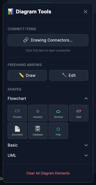
Creating Diagram Shapes
From the Panel
- Open the Diagram panel
- Select a shape category (Flowchart, UML, Network, Basic)
- Click a shape to add it to the canvas
- Drag to position
Shape Categories
| Category | Shapes | Use For |
|---|---|---|
| Flowchart | Process, Decision, Terminal, Data, Document, Database | Flowcharts, workflows |
| UML | Class, Use Case, Actor | Software diagrams |
| Network | Cloud, Server | Architecture diagrams |
| Basic | Rectangle, Circle, Triangle, Star | General purpose |
Connecting Items
Quick Connect (Any Items)
- Select the source item
- Hold Shift and click the target item
- A connector is created automatically
Using Connect Mode
- Click Connect in the Diagram panel (or press C)
- Click on the source item’s port (blue circle)
- Drag to the target item’s port
- Release to create the connection
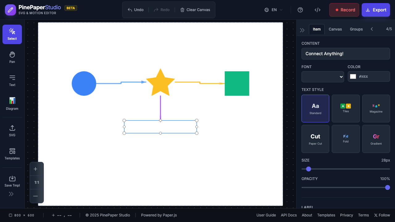
Works With Any Item
Connectors aren’t limited to diagram shapes. Connect:
- Images and imported SVGs
- Text elements
- Custom shapes (circles, stars, rectangles)
- Generator-created elements
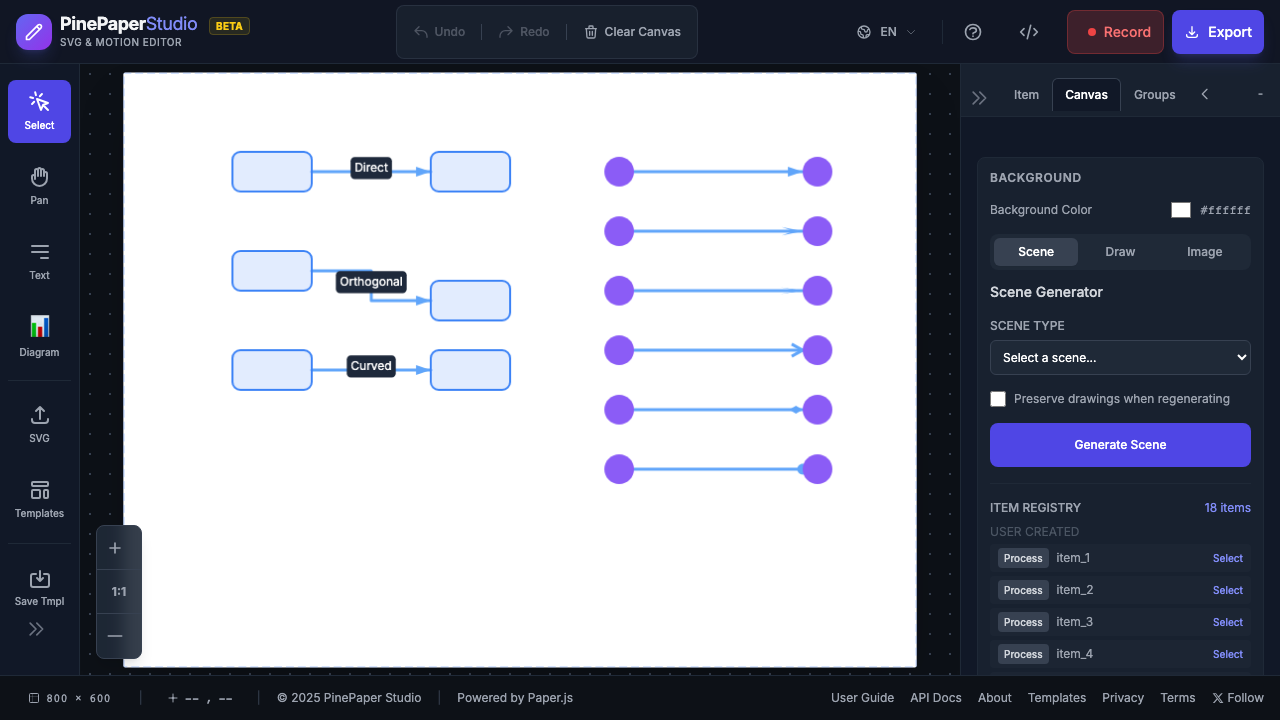
Connector Styles
Routing Styles
| Style | Description | Best For |
|---|---|---|
| Direct | Straight line | Simple connections |
| Orthogonal | Right-angle paths | Technical diagrams |
| Curved | Smooth bezier curves | Organic layouts |
Arrowhead Styles
| Style | Appearance |
|---|---|
| Classic | Filled triangle |
| Stealth | Diamond with notch |
| Sharp | Elongated point |
| Open | V-shape outline |
| Diamond | Diamond shape |
| Circle | Filled circle |
| None | No arrowhead |
Auto-Layout
Automatically arrange your diagram:
- Select the shapes to arrange (or select none for all)
- Click Auto-Layout in the Diagram panel
- Choose a layout algorithm
Layout Types
| Layout | Description | Best For |
|---|---|---|
| Hierarchical | Layered top-to-bottom | Flowcharts, org charts |
| Tree | Parent-child hierarchy | Family trees, file structures |
| Radial | Concentric circles | Mind maps |
| Grid | Regular grid | Inventories, galleries |
| Force-Directed | Physics-based | Network diagrams |
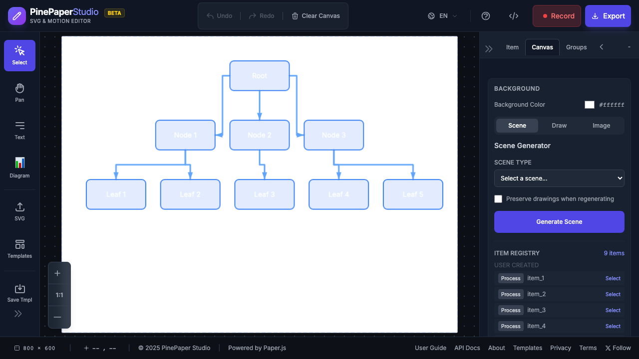
Diagram Examples
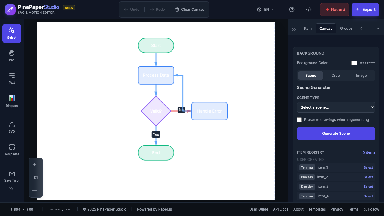
Flowchart
A simple process flowchart with:
- Terminal shapes for Start/End
- Process shapes for actions
- Decision diamond for conditions
- Orthogonal connectors
Network Diagram
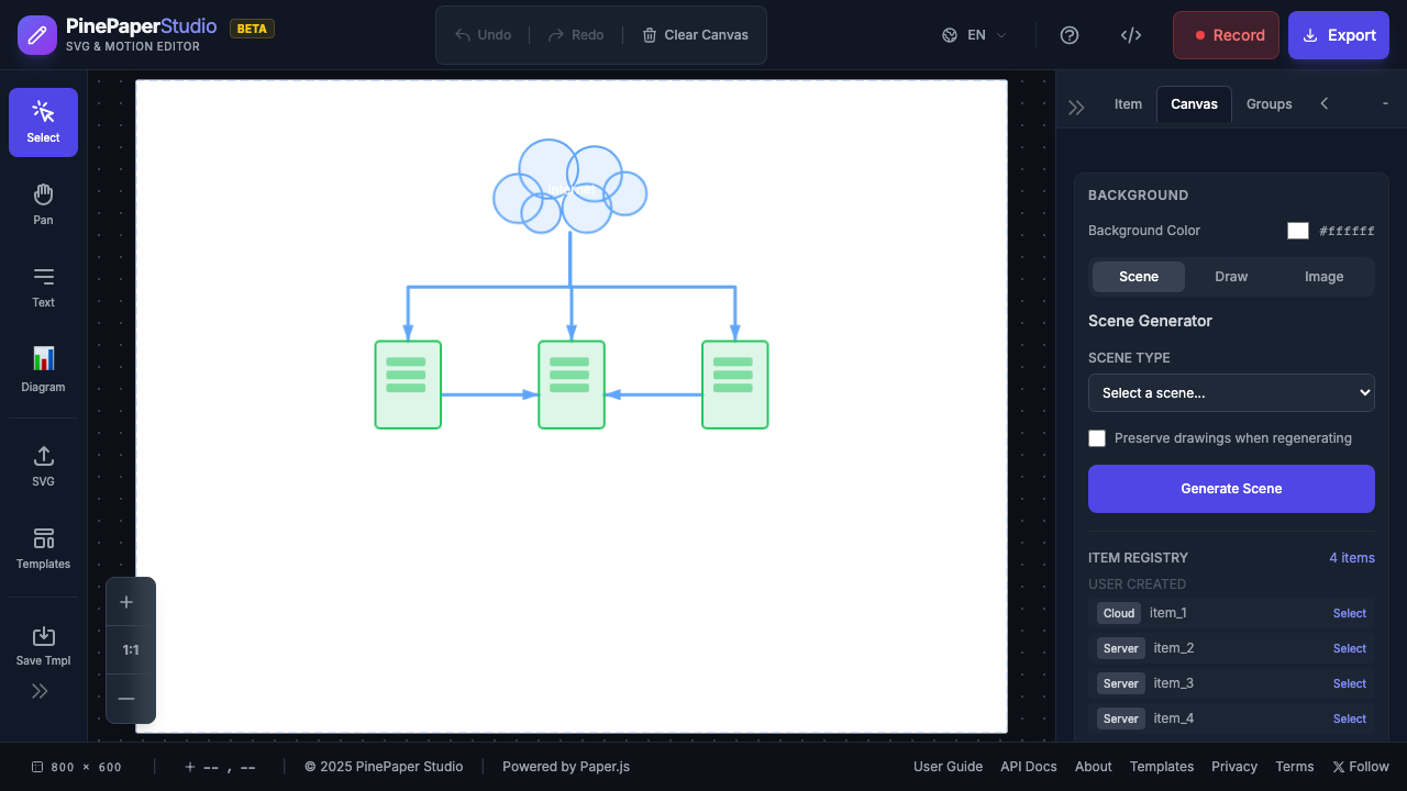
A network architecture showing:
- Cloud shape for internet
- Server shapes for infrastructure
- Dashed connectors for internal links
UML Use Case
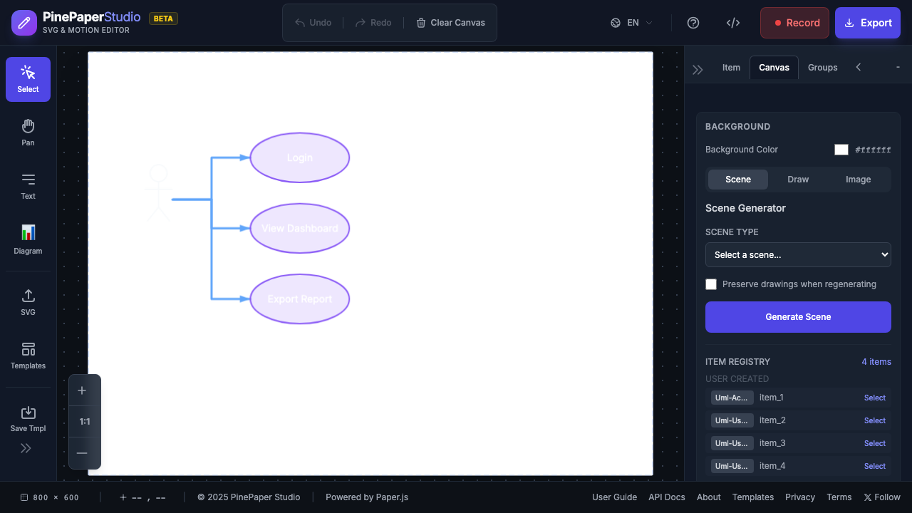
A use case diagram with:
- Actor stick figure
- Use case ellipses
- Association connectors
Animated Connectors
Add the “bolt” effect for animated flow:
- Select a connector
- Enable Bolt Effect in Properties
- Adjust settings:
- Color — Bolt color
- Speed — Animation speed
- Size — Bolt size
The bolt travels along the connector, showing data flow direction.
Tips
Diagram Tips:
- Use orthogonal routing for technical diagrams
- Use curved routing for organic, mind-map styles
- Apply Auto-Layout after adding all shapes
- Hold Shift while dragging for snap-to-grid
Keyboard Shortcuts
| Key | Action |
|---|---|
| C | Enter connect mode |
| Escape | Exit connect mode |
| Delete | Delete selected connector/shape |
Related
- Arrows & Connectors — Legacy arrow tool
- Animations — Animate diagram elements
- Keyframe Editor — Complex animation sequences